Contact Dealer
Compare

FAQs

We know how it feels to quickly need the answer to something. Hopefully you can find what you’re looking for here in our frequently asked questions.

If it is technical assistance you require, we suggest going to your local dealer in the first instance as they will be able to diagnose faults and order parts for you without a fuss. You can also find more useful information in the Auto-Sleepers Owners Club Technical Department.

Q. What is the Auto-Sleeper Job/Serial Number and why you should know yours.

It tells us which vehicle your enquiry is about. Without it we can only make educated guesses and assumptions about your motorhome – with it we can unlock its whole history.

This is often the first thing we ask owners who contact us.  This number is unique to your vehicle and is the key to unlocking all the records we have for it.  This number is the beginning of every motorhome we have ever produced and its creation marks the start of that particular vehicles journey – everything we do that has any link to this motorhome will reference this number. 

You can find it in a few different places.  For early vehicles, up to 2008, it was almost always in the glove box.  Since 2008 the usual position has been on the rear pillar of the passenger cab door frame (B post) although up until 2010 some were located by the original chassis plate in the engine bay or, on some Mercedes and Fiat based vehicles, the side of one of the cab seat bases, the driver’s seat base being likeliest.  There was also a period in the late eighties and early nineties when the numbers were etched onto the windows.

The numbers are combinations of digits and letters.  Early ones had a letter as the year identifier and three or four numerals – A123 or N456 for example – later ones have a type identifier letter M, F, C, P, J and K are the usual ones and this is followed by 4 or 5 numbers usually with a dash and a leading zero; A-07890 for example


Q. My water level gauge is erratic or always reading full.

In a fresh water tank the likeliest cause is a build-up of calcium carbonate (lime scale) on the ends of the sensor probes.  Once removed, either chemically with a lime scale remover or mechanically by abrasion, normal function will return.

Note that this problem is less likely to occur in the waste tank where the usual symptom is a permanent “full” indication whether the tank is full or not.  The likeliest cause is a build-up of waste deposits in the tank making an electrical pathway between the sensors resulting in a false reading.  The easiest way to deal with this is to heavily dose the tank with a liquid biological washing powder and 20ltrs of hot water.  Follow this with 20 minutes enthusiastic driving along your favourite bumpy and twisty country road then drain and flush with clean water.

A less usual cause on both fresh and waste tanks is an electrical pathway formed between the sensors on the outside of the tank.  Give everything a good clean, dry thoroughly and spray liberally with a low viscosity coating.  We use PLASTIK 70 – RS Components if you can’t find it anywhere else.


Q. The central locking doesn’t work on the habitation door.

Since 2021, Mercedes based Auto-Sleepers do not have central locking on the habitation door – this covers all 2021 year models, including those ordered in 2020.

With Mercedes registered circa 2014 – check that the habitation door is the only one that doesn’t lock – if the passenger cab door is also affected the problem almost certainly lies within the Mercedes SAM (signal acquisition module) Note that the cab passenger door not locking is the key diagnostic.

Several types of habitation door are used but the common issues are the same across all types. 

Earlier vehicles have spring loaded contacts on the door and frame that connect the 12v power supply to the locking mechanism – they are usually located at the top left of the door/frame when viewed from inside the vehicle.  Later models are fitted with hard wired electrics - where power enters the door via a wire by the bottom hinge.

The commonest problems are:

  • A fuse has blown in the main fuse board in the power supply unit (EC 357, 500, 700 etc)
  • A fuse or relay has failed in the EM40/45/50; this is normally located at back of driver’s seat base or in the o/s seat box – it’s full of relays and fuses, check the handbooks for their designations and ratings.
  • A break has occurred in the wire between the door and the body of the motorhome – carefully inspect the wire.
  • The contacts are not making properly.  Adjust them to ensure proper alignment and contact.  Deposits formed by electrolysis are common and should be cleaned off with emery cloth/sandpaper/wire pan scrubber.  When testing its helpful to wet the contacts to ensure positive contact. 
  • The control rods connecting the solenoid to the locking mechanism have detached.  In an emergency it is possible to remove the inner door skin to gain access but this is not a job we recommend you attempt – If you do, take lots of photos as you go because it is a real jigsaw puzzle to reassemble.

Q. My step doesn't work

Symptoms are typically that it fails to deploy/retract, it blows fuses, or the buzzer sounds continuously.

Failure to fully deploy or retract is a step count issue.  Too low and it doesn’t come out or go in properly. 

Note the step count can be adjusted in the advance menu on the control panel.  Access to this menu varies but usually involves going to the home screen and pressing and holding the up and down command buttons until the menu appears. Increase the step count one unit at a time (usually displayed as milliseconds) until the desired result is achieved. Note that the recommended default setting is 3600ms.

1. It continually blows fuses. If it doesn’t move at all, its likely that the motor or step mechanism is seized (lack of maintenance) strip it down, clean and lubricate.

2. It continually blows fuses. If it’s moving out and back and the fuse blows at the end of one of the movements the step count is too high – the motor keeps running after the step has reached its limits – decrease the step count as per the instructions for increasing it.

3. It continually blows fuses 3. This applies only to the Sargent 7000 series system.  A 10 amp fuse was originally specified for the step – this has now been upgraded to 15 amp to solve this issue. Swap out the 10amp fuse for one rated at 15amps.

4. Step is stuck out. Check remedies above.  If none fix the problem then intervention is needed to get step back in. 

5. Step is stuck out on coachbuilt models. The step and motor can be disconnected relatively easily (pins and or bolts in the frame) and the step manually returned to its closed position – secure with strong cable ties or cord. 

6. Step is stuck out on panel van model. A cassette step is fitted.  The motor is harder to disconnect and access has to be gained to the underside of the slide out.  With Thule steps pop the two screw covers off and remove the facia and base plate – spring clips at each side underneath are detached to release the slide out.  With older type steps access is via the bottom plate.

7. The buzzer sounds erratically, or continuously, when the step is retracted. The step count is too low to fully open the buzzer switch, see above for step count adjustment. Or the buzzer switch is jammed open by debris, it is protected by a rubber cover which collects road dirt over time; pop the cover of and clean. 

8. The buzzer sounds when the step is closed. A tip for a quick fix for coachbuilts – tape a packer to the top of the step where it contacts the switch so that it’s pushed in a little further.

If all else fails, tracking the buzzer down and pulling a wire off it will at least make for a quiet ride home.


Q. I can't fill my water tank

The wrong settings have been selected on the control panel – check the control system manual for the settings you need to ensure the system is working as you want it to. 

Make sure “both” is selected for the pumps if you are using an external source. A tip, set it up permanently in this mode.

The inlet solenoid is not functioning this is located on the back of the filler and it should be warm to the touch when operating.  Check the voltage to it.  If you don’t have a volt meter you can do this by switching the power on and off whilst holding your finger on it/listening for it to open.

The filter on/in the inlet solenoid is blocked.  This is common – it would appear that site water supplies are very calcium carbonate particle rich – to fix this simply replace the filter.  In an emergency discard the cartridge and reassemble the solenoid – it will get you through your trip without the need for further action but don’t forget to put a new one in when you get home


Q. Why is my gas tank level gauge inaccurate?

The electronic display in the cab is derived from a mechanical gauge in the tank.  A float rises and falls through an arc on the end of an arm in response to the level of the liquid in the tank which has a circular cross section.  This movement is transferred to an analogue dial on the outside of the tank by a magnet and a sensor detects the movement in the dial and uses this to control the electrical current which illuminates the indicator on the dash board.

If gas is used at a constant rate the float falls faster at the top and bottom of its arc but slows through the middle section when the tank is half full in response to the volume to cross section ratio.  The lights on the dashboard are best considered to be an indicator rather than a gauge.  On the plus side, it always indicates that there is less gas in the tank than there actually is – far better than the other way round.


Q. I can’t find an Auto-Gas Supplier?

Try this guide https://lpgstations.com


Q. How long will my gas last?

Your tank holds 20 litres when full. Each produces around 7KWh so you have around 140KWh to use.

When running at full power.

  • The combi heater can use up to 6KWh,
  • The blown air space heater installation can use up to 6KWh,
  • The water heater can use up to 1.5KWh
  • Each of your cooker burners uses 1.5KWH
  • The fridge uses approx. 0.02KWh

In practice, and as a very rough guide, if daily use is something like the combi heater heating the van for a couple of hours and water for a couple of showers, the cooker boiling the kettle three or four times and the oven on for an hour or so  will use around 10KWh giving you up to 14 days use, broadly what you could expect from two 6kg cylinders. 


Q. What tyre pressures do you recommend?

The short answer is that we don’t.

We recommend that you always consult the base vehicle manufacturers (Peugeot, Ford, Mercedes, and Fiat etc.) Owner Manual for this information; it is often available on a sticker attached to the vehicle, normally in one of the cab door shuts. 

The figures the manufacturers provide are calculated to cater for the driving conditions the vehicle can be expected to encounter and the fact that the vehicle has been converted to a motorhome has no bearing on these calculations.

However, should you wish to explore the possibility of running pressures outside those recommended by the base vehicle manufacturer you can consult with the tyre manufacturer.  They will want to know your vehicle type, the total weight in running order (loaded as it would be were you going on holiday), the front and rear axle weights, again in running order, and the specific model of the tyre.  Armed with this information, they may be able to advise a specific pressure range in which they are confident that the tyre will perform as designed.  The decision whether or not to operate at those pressures will be yours and yours alone.


Q. My water pump runs but won’t prime.

There are two common causes; the tank has run dry or the pump primes but doesn’t produce enough pressure to open the non-return valve in the pressure adjustment unit.

The tank has run dry.  When refilled the pump has an air bubble in its inlet and when turned on the impeller spins in the air pocket; the fix is to dislodge the bubble.  There are a number of ways to try and do this. 

First, double check that there is water in the tank, that the dump valve is closed and at least one cold tap is open, then simply run the pump for five minutes; the water in the tank will keep it cool. 

Second, thump the bottom of the water tank, do this at least five times as close to the edge of the heater pad as possible; this is our most successful technique and we have a piece of timber the size and shape of a cricket bat to do the job with – it deliverers the good solid thump needed.

Third, with the pump running and only the cold shower tap open try sucking on the shower hose.

Fourth, drive over a bit of bumpy ground – campsite tracks are ideal - to create a good slop inside the tank.

The other problem is also associated with this tendency of air to get trapped around the impeller – the pump primes but doesn’t produce enough pressure to open the non-return valve in the pressure adjustment unit.  A good remedy is to disconnect the pipe from the pump and very briefly run the pump – this will clear the air from the impeller.  When the pipe is reconnected and the pump switched back on it will generate enough pressure to open the non-return valve.  Note that you should expect a squirt of water from the pipe, half a cup if you are quick with the off switch, so cover the end with a towel.


Q. Why are my window glazing units steaming up?

The windows are double glazed sealed units made of PMMA.  This is a material which allows a process known as condensate diffusion to take place and under certain conditions this will causes condensation to appear and disappear inside the sealed glazing unit.  This is a normal natural event and the condensed water will gradually disappear without any outside intervention.  The condensation appears because there are effectively three climate zones: one inside the vehicle, one inside the glazing unit, and a third outside the vehicle and the humidity in the atmosphere is naturally try to balance the three. Because PMMA is a material which allows condensate diffusion the humidity inside the glazing unit can slowly rises and falls in response to conditions inside and outside the vehicle.  Sometimes the humidity level in the unit is high enough that cooling one side of the unit – outside for example as the temperature drops in the evening – will cause condensation to form on the inner surface of the outside pane only to disappear in the morning when the temperature outside rises to the point when the condensate re-vaporises.

It is generally accepted that a 3mm thick window pane can allow 0.3 grams of water to pass through within 24 hours.

To minimise the likelihood of this phenomena occurring it is worth noting that good air circulation is the most effective preventative.  It keeps the humidity inside and outside the motorhome in balance reducing the potential for diffusion.

In extreme cases removing any plastic plugs and carefully pressing the window panels together (panting the glazing unit) will speed-up the vaporisation and removal of the condensate – choose a warm dry day.  Whatever you do don’t use a compressor directly on the holes it will blow the unit apart.


Q. I have found some small round black switches in one of the seat boxes of my 1990-2013 Auto-Sleeper, what are they for?

These control the optional water and waste tank heaters.  If you are not sure if you have the heaters look at the ends of your tanks – if there are heaters fitted you will see a brass fitting with a nut that has two wires leading from it – they are always as close to the bottom of the tank as possible.)

Some of these switches are illuminated some are not – on/off is as per normal convention. Out at the top is on.  Note the heater is thermostatically controlled and will not come on unless the temperature approaches four degrees C.

Note that since 2013 we have used heater blankets controlled via the control panel.


Q. Lithium batteries

  1. My battery has gone flat and when I start the engine the charging circuit fuse blows.

One of the principal advantages of a lithium battery is its discharge characteristics – it keeps supplying good amp/volts far deeper into its discharge cycle than a comparable lead acid battery but if it’s pushed too far the internal voltage drops far more quickly than with a lead acid type.  The very low internal voltage that results demands a very high charge current when one becomes available – i.e. you start the engine or switch on the battery charger.  The battery chargers recognises this and modulates the current to prevent fuses being put under too much stress but the alternator only sees a demand that it tries to satisfy and this can over stress the fuse and it blows.

The solution is to recharge the battery using the 230 charger.  Once recharged just keep an eye on the battery level and if it starts to get close to – either switch the battery charger on or start the engine to top up.

Check also that the fuses in the charging circuits are rated at 25 amps – some early installations were fitted with 20 amp fuses that have since been uprated to cater for the higher charging ampage.

  1. I have read that lithium batteries cannot be safely charged it the temperature falls below zero Celsius.

When charging LifEPO4 batteries below 0°C there are some important things to consider.

Lithium battery manufacturers often quote an operational temperature range of -20°C to +55°C. However; a common misconception with this is that this is a safe temperature range for both charging and discharging but this is not the case.  The temperature range refers only to discharging.

When attempting to charge these batteries below 0°C, a chemical reaction can occur resulting in an increased accumulation of lithium ions on the surface of the anode.  This can, over time, reduce the rate of chemical metabolism and cause a reduction of the battery’s capacity. This damage will compound each time low temperature (zero degrees C or lower) charging occurs.

Charging a Lithium battery at temperatures below 0°C should be avoided unless your battery is designed to specifically manage this. Typically this would be by a Battery Management System (BMS) that included an internal heater.  Below 0°C the BMS will divert the charging current to the heater until the temperature of the battery reaches 5°C when normal charging commences.

Not all batteries have this protection included, so it important to check. Which type you have.  Of the three battery types fitted by Auto-Sleepers, 60AH, 85AH and 100AH, only the 100AH is fitted with this system.  The 60 and 85AH types do not have this feature.

Auto-Sleepers does not consider this to be an issue given the low probability of the temperature inside the vehicle being below zero whilst the battery is being charged.  Note that we have been monitoring the temperatures in a range of vans right across the British Isles this winter to verify his and have found that temperatures below zero inside an Auto-Sleeper is actually an unusually rare event.

Note also that we have been using these batteries since the beginning of 2021 and have no evidence that low temperature charging has been an issue nor do we expect it to become one. 


Q. How do I fill my LPG tank?

LPG RE-FUELLING

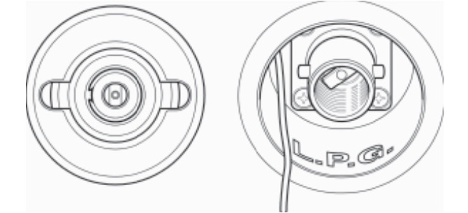
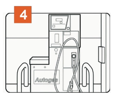
LPG re-fuelling is simple and efficient, carried out in much the same way as petrol and diesel with a hose and nozzle designed to lock onto the filling connector on the vehicle. The refulling point is located behind a black plastic cover on the offside of the vehicle behind the driver’s door.

Once the connection is made, the customer simply presses and holds down a button on the dispenser until they have put the required amount of fuel into the vehicle or until the tank is full.

LPG tanks are fitted with a valve that stops the flow once the tank has reached its maximum safe filling level. Once the meter stops the customer simply disconnects the nozzle and returns it to the dispenser.

Note: Although the nominal capacity of the tank is 25 litres, a float valve automatically cuts off at 80% full to allow space for the gas vapour above the liquid. Therefore, the maximum amount of LPG which can be put into the tank is 20 litres.

There is a gauge for the LPG tank, fitted at the right hand side of the dashboard, which uses LED lights to indicate the fuel level.

Safety Note

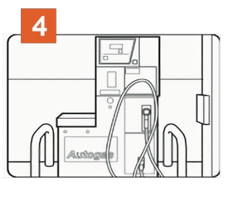
When arriving at the Autogas dispenser ensure the vehicle is parked
with the filling connector located nearest to the dispensing pump.

  • Apply the handbrake and switch off the engine. If the Combi space heater is running it will turn off automatically. It will need to be re-started at the control panel after the engine has been re-started.
  • No smoking, naked flames or mobile phones are allowed on the Service Station forecourt.
  • If the re-fuelling process will take longer than 15 minutes (ie with the ignition off) then turn the refrigerator off at its main switch in order to prevent it from switching automatically to the alternative energy sourceof gas and producing an ignition spark.
  • The use of an adaptor is not recommended.


FILLING NOZZLES

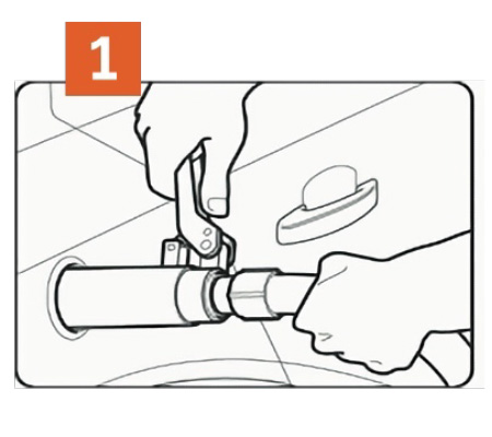
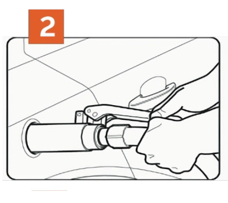
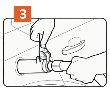
When connecting the nozzle to the filler valve on your vehicle always check that the locking pins are aligned. There are two main types of filling nozzles used in the UK - ‘Gas Guard’ and ‘De
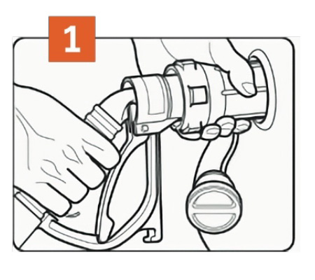
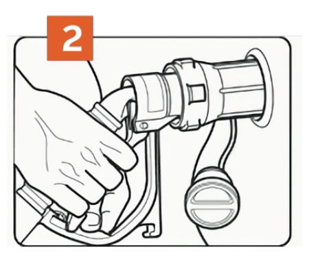
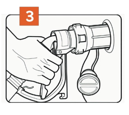
Visser’. Gas Guard uses a rotating barrel to lock on to the filler valve whereas De Visser uses a lever.


Gas Guard nozzle filling instructions
Ensure Gas Guard nozzles are fitted with protective nozzle shields. Report to site staff if missing. (Nozzle shields have been removed from picture for clarity).

Connecting:Push nozzle over the lugs on the filler valve and turn barrel a quarter turn clockwise to lock.

Do not squeeze lever before nozzle is connected.

Caution: From this moment onwards ensure hands are away from the nozzle barrel.


Pull back lever and latch into place. Ensure lever is latched securely. Follow instructions on dispenser to
commence dispensing.


Disconnect: Ensure hands are away from the nozzle barrel. Caution: When dispensing has ended, squeeze back lever and release latch. Release lever fully. A small release of gas will occur as you release the lever. This is normal! Do not place hands on barrel until after the gas has been released


Turn barrel anti clockwise a quarter turn to release nozzle from vehicle. Replace nozzle in holder on dispenser.


De Visser nozzle filling instructions
Ensure Gas Guard nozzles are fitted with protective nozzle shields. Report to site staff if missing. (Nozzle shields have been removed from picture for clarity).

Connecting: Hold the hose behind the nozzle and the guard, keeping lever pushed forward with the handle at 12 o’clock position. Locate the nozzle over the lugs on the filler valve and turn the lever a quarter turn clockwise to lock.


Pull back lever towards hose and latch into place. Ensure lever is latched securely. Follow instructions on dispenser to commence dispensing.


Disconnect: Ensure hands are away from the nozzle barrel. Hold hose behind guard and release lever by pushing forward. A small release of gas will occur as you release the lever. This is normal, place hands on barrel until after the gas has been released.


Turn lever anti clockwise a quarter turn to release nozzle from vehicle. Replace nozzle in holder on dispenser.

Please Note

  • For European touring, adapters for use with the UK bayonet filling connector may be used temporarily.
  • Refilling of portable LPG cylinders is not allowed.
  • All dispensing nozzles

Back to Owners

You may also like...

Mercedes

M-Star

Add to compare
From
£125,250
View More
Berths: 2
Seats: 2
Peugeot/Fiat

Nuevo EK Plus

Add to compare
From
£80,730
View More
Berths: 2
Seats: 2
Mercedes

Malvern

Add to compare
From
£108,450
View More
Berths: 4
Seats: 2